LiDAR APPARATUS
Invented by BYUN; Hyunil, KIM; Woosung, LEE; Changbum, SAMSUNG ELECTRONICS CO., LTD.
LiDAR is getting smarter, faster, and smaller. In this article, we unpack a new patent application for a LiDAR system that uses clever tricks to steer light and see the world in 3D. If you’re curious about how LiDAR is changing and what makes this invention stand out, you’re in the right place.
Background and Market Context
Technology is moving fast, especially for cars and robots. Many new cars have smart helpers like adaptive cruise control and automatic emergency brakes. These helpers need to know what’s happening around the car, so they use sensors. LiDAR, which stands for Light Detection and Ranging, is one of these sensors. It works by sending out tiny beams of light, waiting for them to bounce back, and then figuring out how far away things are.
LiDAR is important because it helps machines “see” the world. It builds a 3D map of everything nearby. This is useful not just for cars, but for drones, robots, security cameras, and even smart home devices. As more cars try to drive themselves, LiDAR is becoming even more critical. Companies want LiDAR that is fast, accurate, small, and cheap. They also want LiDAR that can handle tough jobs, like spotting small objects or working in bright sunlight.
But there are challenges. Old LiDAR systems use moving parts, which can break or wear out. They can also be bulky and expensive. Newer LiDARs try to use chips instead, with no moving parts. These are called “solid-state” LiDARs. They use clever ways to steer the light, like changing its path on a chip. But getting these chips to work well and cover a wide area is hard. This patent application tackles these problems head-on, with a new way to steer light using something called a “focal plane array.”
Scientific Rationale and Prior Art
To understand what’s new, let’s first see how LiDAR usually works. Traditional LiDAR sends out a laser beam, spins it with a mirror, and detects the reflected light. This spinning mirror scans the world. But mirrors can break, and spinning takes up space. That’s why researchers looked for ways to steer light without moving anything.
Solid-state LiDAR tries to solve this by using chips with tiny optical waveguides. These are like tiny roads for light. By switching parts of the chip on and off, you can send the laser out in different directions. Some systems use something called an “optical phased array,” which can steer light by changing its phase. Others use small mirrors on chips, or even special materials that bend light.
A big problem is getting high resolution – seeing small objects – and a wide field of view. Chips have to fit lots of tiny pieces close together. Also, the system needs to control many lasers or light sources, each with different colors or wavelengths, without mixing them up. Some older patents use single waveguides with many switches, but this can limit how wide the scan is or how sharp the image is.
Another challenge is timing. When you turn on a switch to send light out, it takes a moment to settle. If you go too fast, the system might get confused, or signals might overlap. Too slow, and your LiDAR is not quick enough for real-time tasks.
The prior art also struggles with integrating everything on one chip. You need lasers, switches, detectors, and maybe even tiny lenses, all on a small piece of silicon. Some patents have tried, but often with trade-offs in performance, size, or cost.
This new invention looks at these problems and tries to make a LiDAR system that is both smart and simple. It uses clever switching, works with many light wavelengths, and puts all the parts together on a single chip. The goal is a LiDAR that doesn’t just work for cars, but also for phones, robots, and even smart refrigerators.
Invention Description and Key Innovations
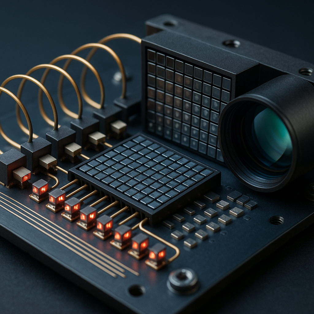
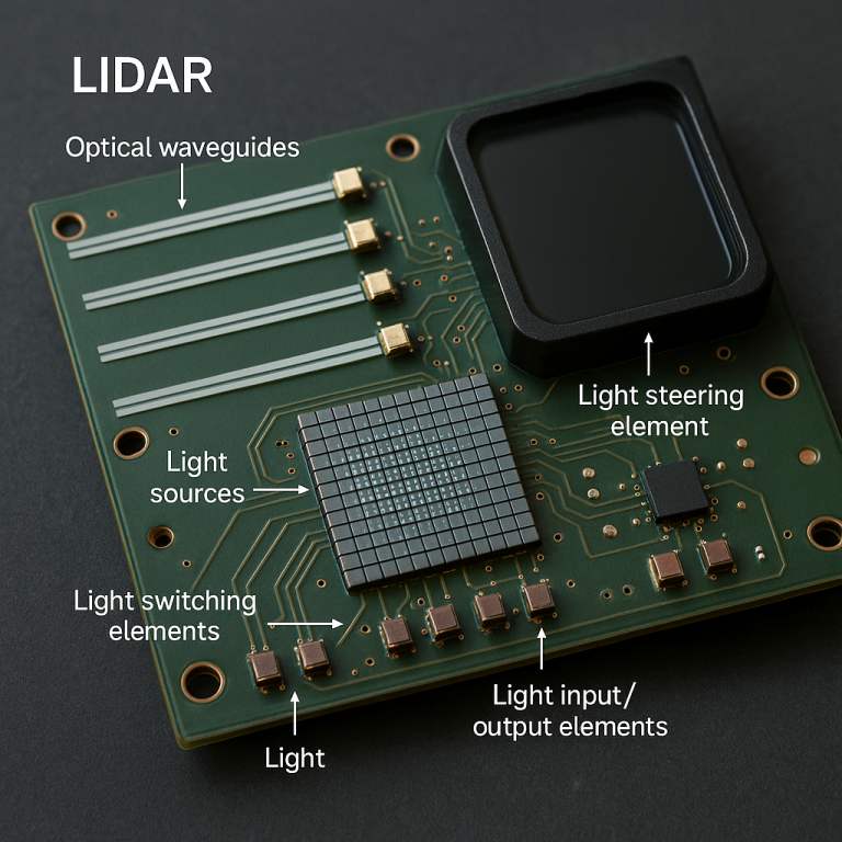
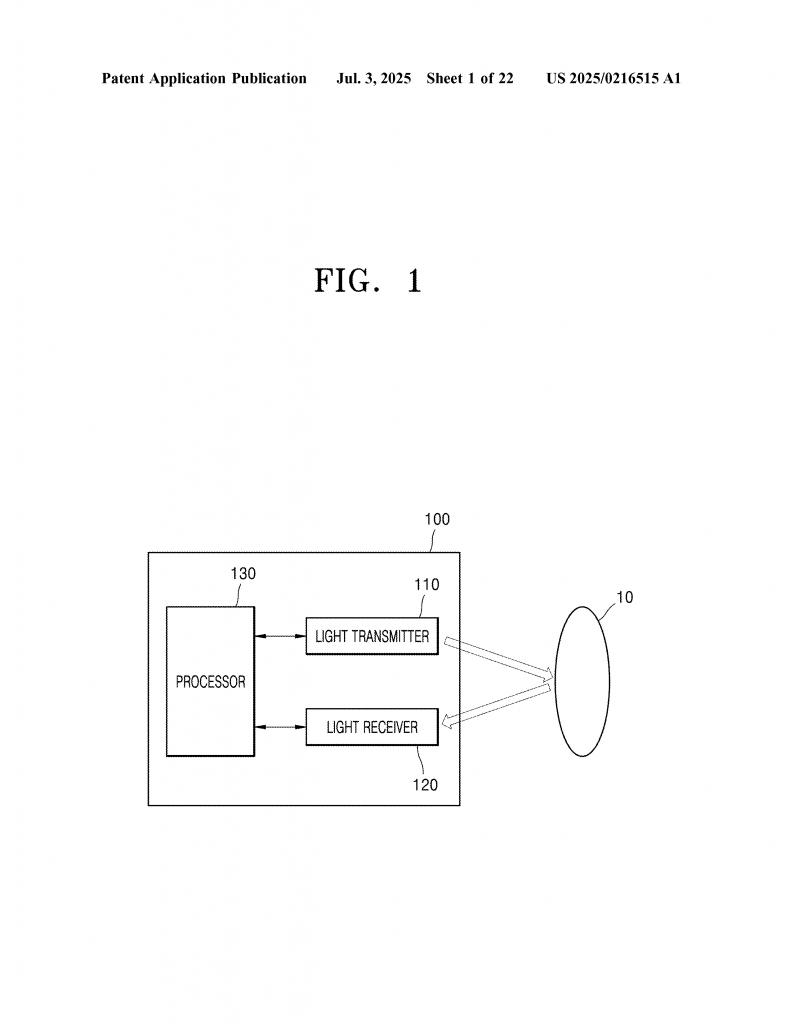
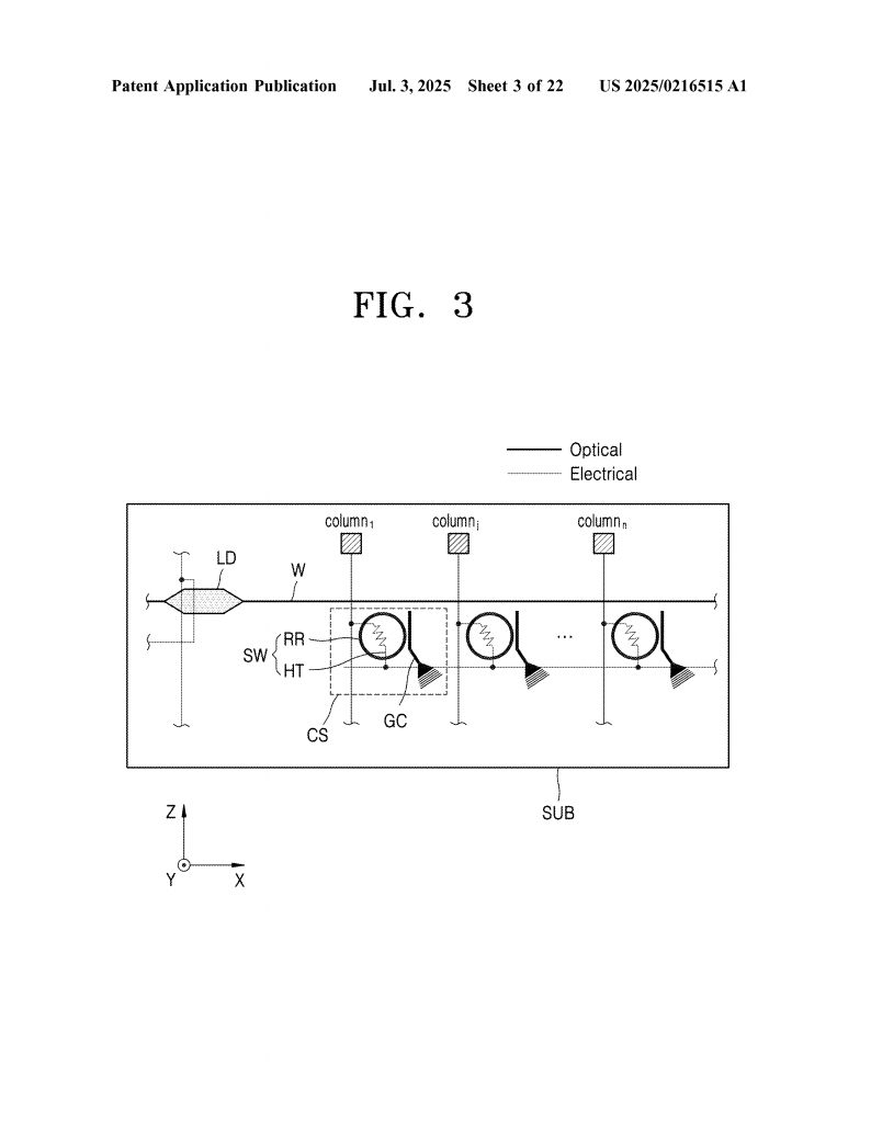
Now let’s get into the heart of this new LiDAR invention. The system uses a set of waveguides, light sources, switches, and a special steering element, all placed in a neat grid on a chip. Here’s how it works in simple terms:
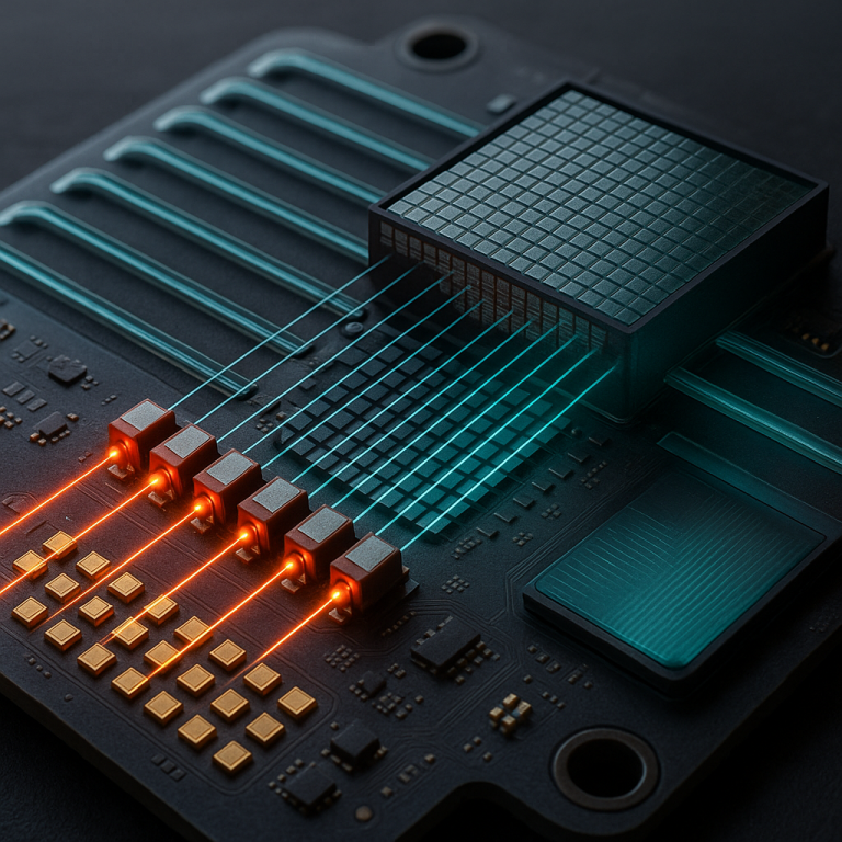
Imagine a chip with tiny light roads – these are the waveguides. They stretch in one direction. Along them, there are light sources, each spaced out in another direction. Each light source connects to a waveguide. This setup lets you use many light sources, each with its own color or wavelength, making the system flexible and powerful.
Between the waveguides and the outside world, there are two-dimensional grids of light switches. These switches decide where the light goes. Each switch can connect a waveguide to a light input/output element. These elements are like tiny windows that send the light out or catch reflected light coming back.
The magic happens when you control which switches are on or off. By turning them on and off in a certain order, and by using light from different sources, you can scan the world in both horizontal and vertical directions. This is called two-dimensional scanning. It’s like having a camera that can look left-right and up-down, but using light beams instead of pixels.
At the end of this system is a light steering element. Think of it like a tiny lens or mirror. Depending on where the light hits this element, it gets bent in a certain direction. This allows the system to scan a wide area without any moving parts. The steering element can be shaped like a lens, and it works with the grid of light input/output elements to cover both azimuth (side-to-side) and elevation (up-and-down) angles.
One clever feature is that the light sources can all have slightly different colors (wavelengths), and the system can use these differences to help steer and control the beams. The switches can be fine-tuned so that only the right light gets through at the right time. This is done using something called a ring resonator, which acts like a tiny filter for each beam of light. The tuning elements can make small changes, so everything stays in sync.
Timing is also handled smartly. The system can overlap the control signals for different switches a little bit, as long as it doesn’t cause confusion. This makes the whole LiDAR scan faster, because there’s no wasted time waiting for each switch to settle before starting the next one.
The patent also describes the use of light input/output elements that can be either diffraction-based (using patterns to bend light) or mirror-based (using tiny mirrors to reflect light). This gives the designer flexibility to choose the best option for each application.
On top of all this, the system can include extra parts like amplifiers (to boost the light), attenuators (to dim the light if it’s too strong), and even monitoring detectors that help keep everything calibrated. All these parts can be put on the same chip, making the LiDAR very small and efficient.
This new design can work in many devices, not just cars. The patent shows it being used in smartphones, tablets, laptops, home appliances, security cameras, and robots. This means the technology is not just for high-end vehicles, but could be in your pocket, your home, or your workplace.
To sum up, the key innovations are:
– A grid of waveguides and light sources for flexible, multi-wavelength scanning.
– Two-dimensional arrays of switches that let you steer light in both directions.
– A steering element (like a lens) that bends light depending on where it enters.
– Careful timing and switching to make the scan fast and accurate.
– The ability to put everything on one chip, making the system small, strong, and ready for many uses.
Conclusion
LiDAR is the eyes for our smart machines. This new patent shows a big step forward, using simple but powerful ideas to make LiDAR faster, smaller, and more useful. By steering light in clever ways, using grids of switches, and putting all the parts together on a chip, this invention could help LiDAR show up everywhere – not just in cars, but in phones and homes too. As the world moves toward more automation and smart sensing, LiDAR like this will be a big part of making technology safer, more aware, and more helpful.
Click here https://ppubs.uspto.gov/pubwebapp/ and search 20250216515.