IMMERSED POLARIZERS FOR OPTICAL STRUCTURES
Invented by Arbore; Mark A
Optical technology is everywhere—from the smartphones in our pockets to the solar panels on rooftops. A newly filed patent application introduces a clever way to build optical structures that use special polarizers made from metal nanowires. In this article, we’ll walk through what this invention means, why it matters, and how it builds on past ideas, all in clear and simple language.
Background and Market Context
Light is at the core of so many modern devices. Think about cameras, screens, sensors, and solar cells. These gadgets need to guide, shape, and control light to work their best. One key way to do this is by using a polarizer. A polarizer is a filter that lets only certain directions of light waves pass through, like the lenses in polarized sunglasses that cut out glare from water or roads.
In many electronic and optical devices, polarizers are not just useful—they’re necessary. They help screens look brighter and clearer. They make cameras take sharper pictures, especially in tricky lighting. They help sensors “see” more accurately by reducing unwanted reflections or glare. They even make solar cells gather more sunlight by keeping light focused just right.
But there’s a problem: every time light passes from one material to another, some of it gets lost. It bounces off, or gets absorbed. This is called “reflection loss.” Over time, as devices get smaller and smarter, these tiny losses add up and can really hurt performance. For companies making high-tech products, even a small improvement in how much light gets through can mean a big leap ahead of the competition.
That’s why inventors and engineers are always looking for new ways to build better polarizers and to fit them into new kinds of optical structures. The goal is to let as much of the “good” light through as possible, while blocking or minimizing the “bad” light. The new patent we’re looking at today is all about making those improvements real, using some surprisingly simple ideas in a very smart way.
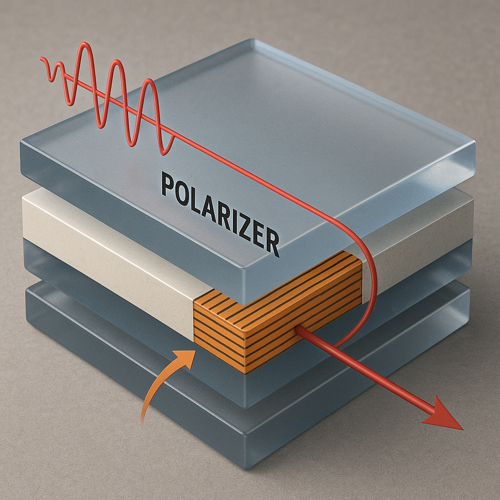
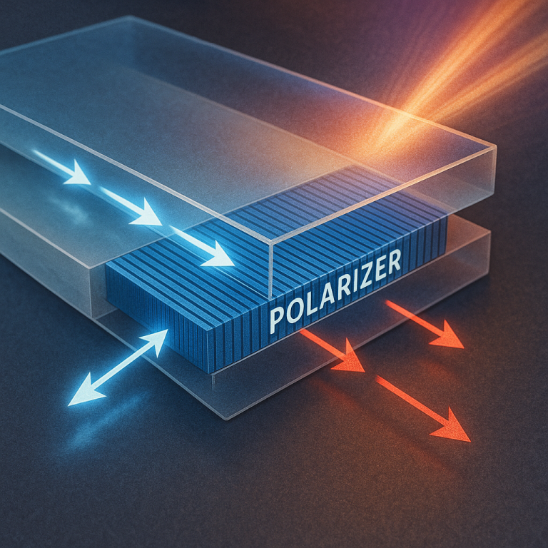
This patent focuses on a type of polarizer called a “wire grid polarizer,” which uses rows of very thin metal wires. These are much smaller than a human hair—so small, you can’t see them without a microscope. They are arranged close together with a special filler material in between. When light hits this grid, only the light waves lined up in the right direction can get through. All the rest is blocked or reflected away.
The trick is to put this polarizer between two other layers in a way that makes the transition for the light as smooth as possible. When you “match” the optical properties (called refractive index) of the layers, you lose less light and your device works better. This patent lays out several ways to do exactly that, opening up new paths for better screens, sensors, lenses, and more.
Scientific Rationale and Prior Art
Let’s look closer at why this approach is clever, and how it builds on what’s come before.
First, a quick refresher: when light moves from one material (like glass) to another (like air), it changes speed. This change is measured by something called the “refractive index.” If there’s a big difference in refractive index between two materials, some of the light will bounce back instead of going through. This is why, for example, you see your reflection in a window at night—the light from inside your house bounces off the glass because of the refractive index mismatch between glass and air.
Old-school polarizers did their job, but they often caused a lot of this bouncing, which meant lost light and poorer performance. They were also usually made as stand-alone pieces, stuck onto or inside devices, making it hard to shrink things down or to keep them working well as devices got smaller.
Wire grid polarizers changed the game by using rows of nano-sized metal wires. These wires are so close together that for the right kind of light, the grid seems almost like a smooth sheet. Light that “lines up” with the wires gets through; light that doesn’t is stopped. This is called polarization. Wire grid polarizers work best when the wires are much smaller than the wavelength of light they’re dealing with.
Earlier inventions in this space focused on the wires and the material between them—the “filler.” People tried different metals, different fillers, and different ways to make the grids. There were also attempts to stick the polarizer onto other layers, or to sandwich it between glasses or plastics. But there was still a problem: the polarizer itself has a sort of “average” refractive index, depending on the metal, the filler, and how much of each is used. If the layers touching the polarizer don’t match this index, you still get unwanted reflection and loss.
Some past methods tried to use anti-reflection coatings or stepped layers, but these added complexity and cost. Others used fancy materials that were hard to make or too expensive for wide use. What was missing was a simple, flexible way to build a polarizer into a stack of layers so that the light passes smoothly, with as little loss as possible, and with materials that are easy to get and to make.
The new patent takes lessons from all these past efforts but puts a new twist on them. By carefully matching the refractive index of the polarizer (using both the metal wires and the filler) to the layers on either side, and by making the structure in a way that lets light “step down” smoothly from one layer to the next, the inventors found a way to keep more light moving in the right direction. This means less lost light, brighter screens, sharper sensors, and more efficient solar cells.
This isn’t just about making polarizers work better. It’s about building them in a way that fits right into the manufacturing process for all kinds of devices, from chips to lenses. By choosing common materials—like silicon, silicon oxide, silicon nitride, and metals like aluminum or copper—the approach is ready for mass production and can be mixed and matched for different jobs.
The patent also describes clever ways to make the polarizer and the other layers “coplanar.” That means parts of the first layer (besides the polarizer itself) can be made from a material that matches the refractive index, filling in spaces or patterns as needed. This opens up even more design freedom, letting engineers shape the path of light in new ways without adding more steps or costs.
In sum, the science here is about controlling light at the smallest scales, using a mix of metal and transparent material, and matching everything together so that light flows smoothly from start to finish. This builds on years of research into optical coatings, nano-materials, and device integration, but takes a practical and flexible step forward.
Invention Description and Key Innovations
Now, let’s break down exactly what the patent claims, and why these steps matter.
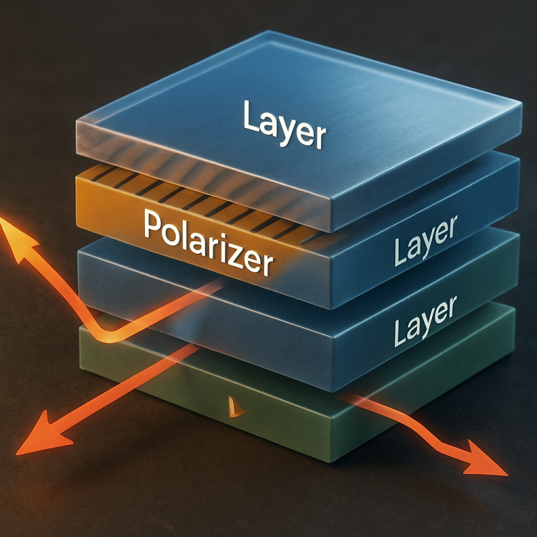
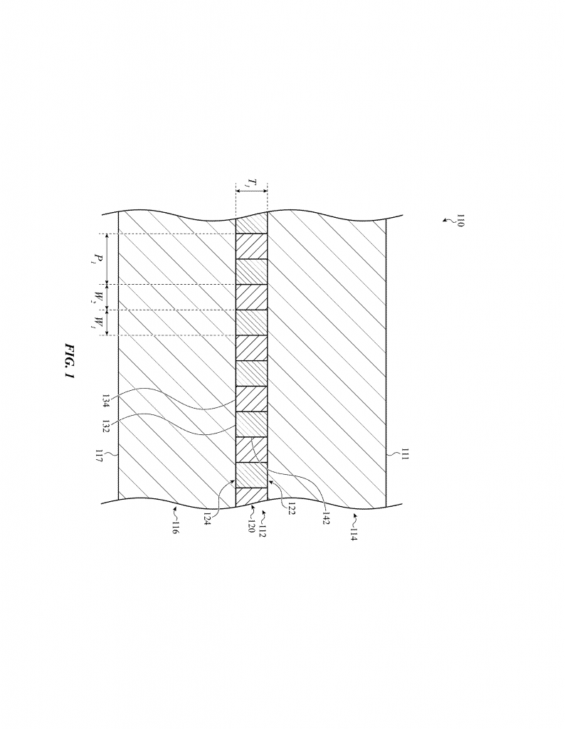
At its core, the invention is a layered optical structure. In the middle is a polarizer made from an array of thin metal nanowires, sitting in a filler material. On either side of this polarizer are other layers, each with specific choices for their refractive index. The goal is to make the “jump” in refractive index from one layer to the next as gentle as possible, to keep the light moving forward with minimal reflection or loss.
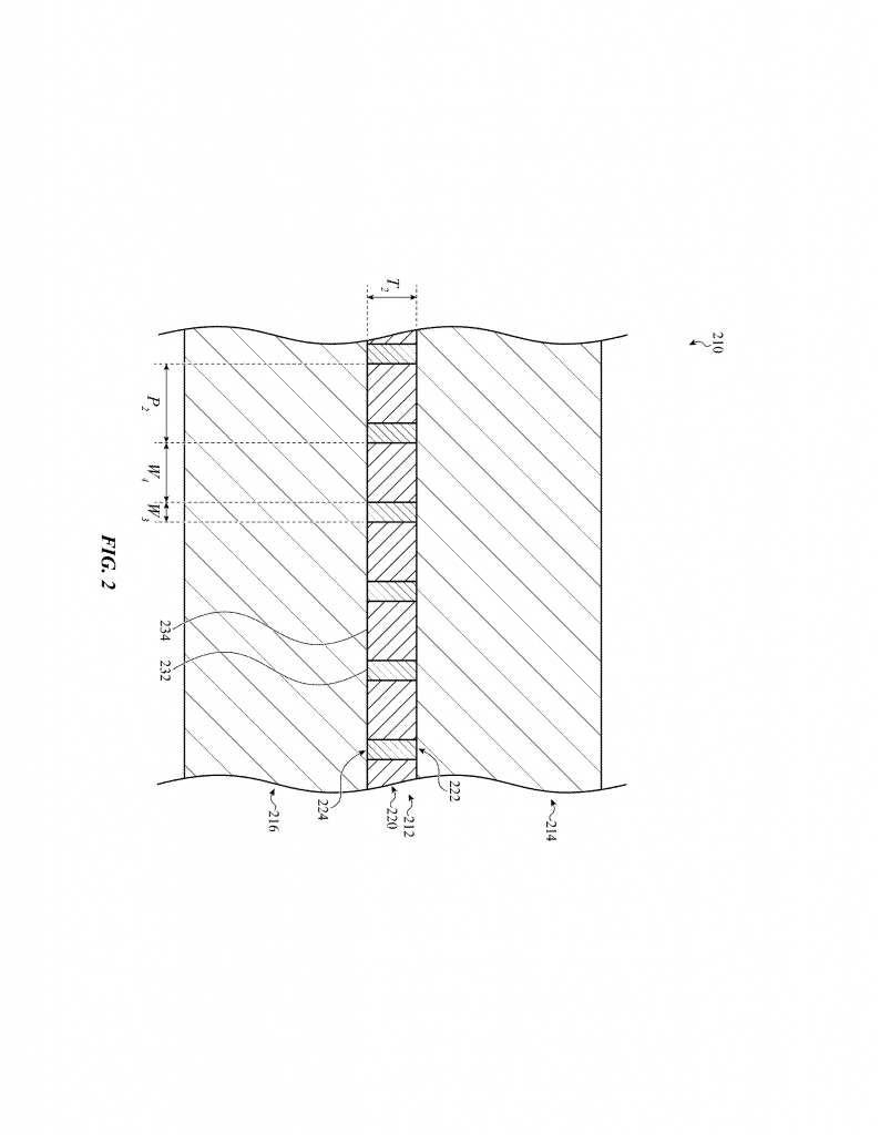
The polarizer is special because it doesn’t just act as a filter—it has its own “effective” refractive index. This is an average, based on both the metal wires and the filler between them, and the proportion of each (called the “duty ratio”). By picking the right widths for the wires and the spaces, and the right materials, the inventors can tune this index to match the layers around it.
The claims cover several ways to build these structures. For example:
– The filler can be a dielectric, like silicon oxide or silicon nitride.
– The metal wires can be made from aluminum, copper, chromium, tungsten, or even other metals or alloys.
– The layers on either side of the polarizer can be made from semiconductors (like crystalline or amorphous silicon) or other dielectrics.
– The “duty ratio” of metal to filler can be adjusted (for example, between 0.2 and 0.5) to fine-tune the refractive index.
In some designs, the layers on either side of the polarizer are made from the same material, so the refractive index matches perfectly. In others, there’s a “step-down” effect: the input layer has the highest index, the polarizer is in the middle, and the output layer has the lowest. This is useful for letting light out into the air or another low-index material, again minimizing reflection.
Another clever feature is the idea of making parts of the first layer (besides the polarizer) from a material that matches the polarizer’s index. This lets engineers fill in spaces or make patterns without messing up the optical performance. It’s like building a puzzle where all the pieces fit perfectly, even if they’re made from different materials.
The patent also covers many variations. For example, the polarizer can be part of a lens, a waveguide, a sensor, or even a light source like a micro-LED or laser. The structure can be made thicker or thinner, and the materials can be swapped to suit different wavelengths—visible, infrared, or others.
What makes this invention stand out is its flexibility and simplicity. It doesn’t rely on exotic materials or complicated manufacturing. Instead, it uses common materials in new combinations and geometries, making it practical for real-world products. By focusing on matching refractive indices and controlling the flow of light, it solves a stubborn problem that has limited optical device performance for years.
For device makers, this means:
– Less light lost at each interface, leading to brighter and more efficient devices.
– Easier integration into existing manufacturing lines, since the materials and processes are familiar.
– More design options for shaping and controlling light, which can lead to new features or smaller, thinner devices.
For consumers, the benefits could show up in brighter phone screens, better camera sensors, more efficient solar panels, and smarter sensors in everything from cars to medical devices.
In summary, the key innovations are:
– Using a wire grid polarizer with a tunable effective refractive index.
– Matching the polarizer’s refractive index to the surrounding layers to reduce loss.
– Allowing for “step-down” transitions where needed for light output.
– Building the structure with common materials that are easy to make and work with.
– Enabling new designs by making parts of the layer coplanar and index-matched.
Conclusion
This patent marks a step forward in optical design, offering a flexible and practical way to build better polarizers into all kinds of devices. By focusing on the simple idea of matching refractive indices across layers, and by using smart combinations of metals and dielectrics, the inventors have found a way to keep more light moving where it’s needed. This can lead to brighter, sharper, and more efficient devices, and opens the door to new ideas in optics. For anyone involved in making or using optical technology, this is an innovation worth watching.
Click here https://ppubs.uspto.gov/pubwebapp/ and search 20250216592.